Senior Design Capstone: Autogyro
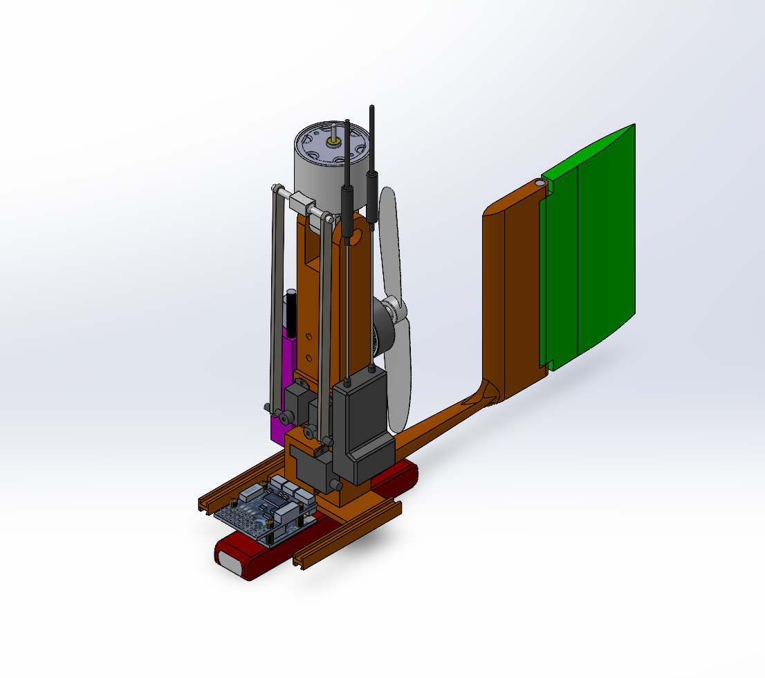
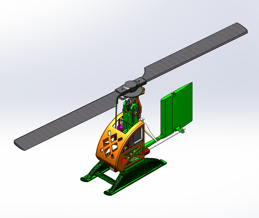
The project started with the first CAD concept of the autogyro, where the main structural layout and component placement were established. This stage focused on defining the fuselage, canopy region, tail structure, and rotor support geometry to create a workable foundation for the rest of the design process.
1. Initial Design
The project began with the first autogyro concept, where the initial structural layout, canopy placement, and rotor-support geometry were established. At this stage, the focus was on developing a workable starting point that could be manufactured, tested, and used as the basis for later design improvements.
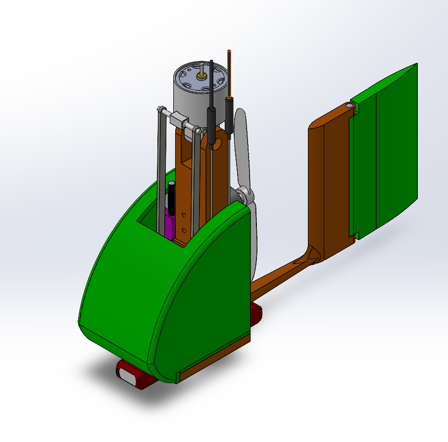
2. Challenges and Areas for Improvement
After reviewing the first concept, it became clear that the design required further refinement in both structure and efficiency. Early concepts included areas with excess material and incomplete integration, so multiple canopy and body configurations were explored to reduce weight, improve manufacturability, and create a more practical overall design.
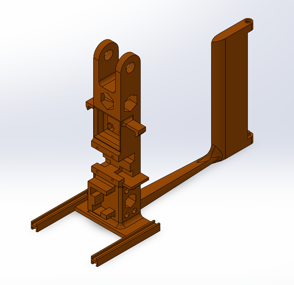
3. Design Iterations
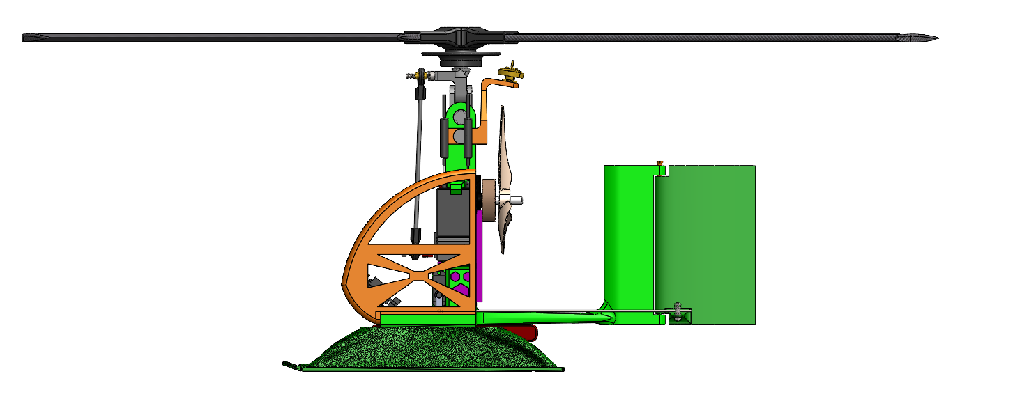
Once the main improvement areas were identified, the design moved into a more developed stage. These iterations focused on refining the canopy and fuselage geometry, improving the overall aircraft profile, and integrating the rotor system more effectively into the design. During this phase, all prototype parts were first printed in PLA so the layout, fitment, and geometry could be evaluated before moving to the final material.
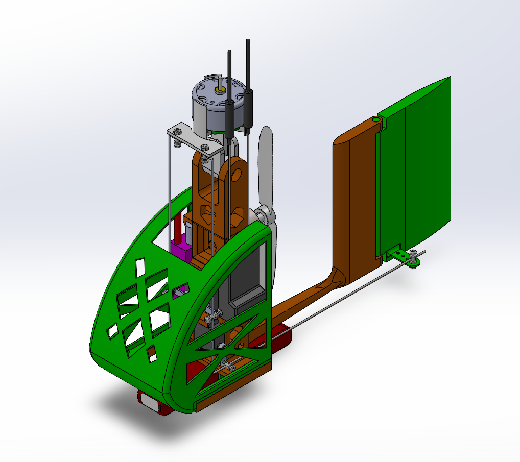
4. Final Outcome
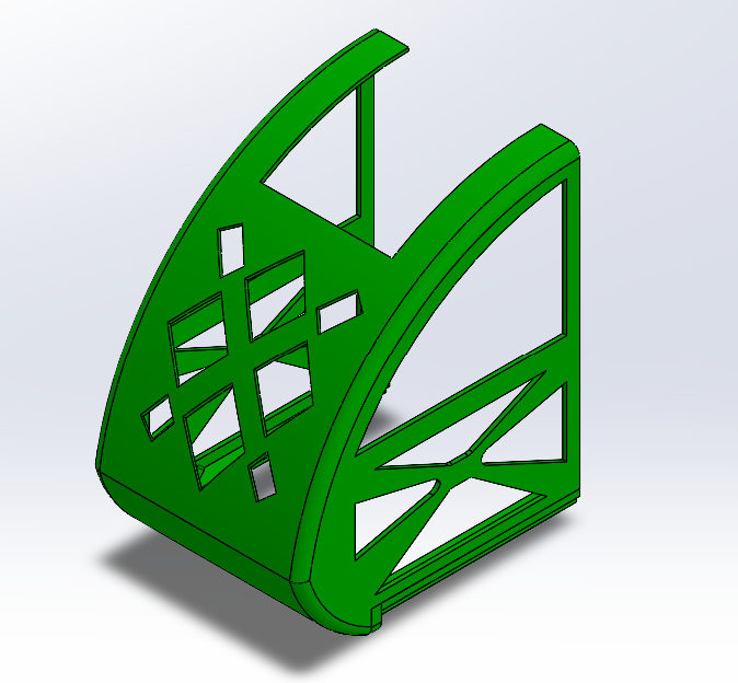
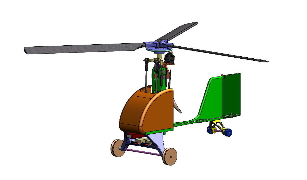
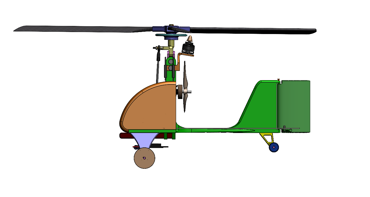
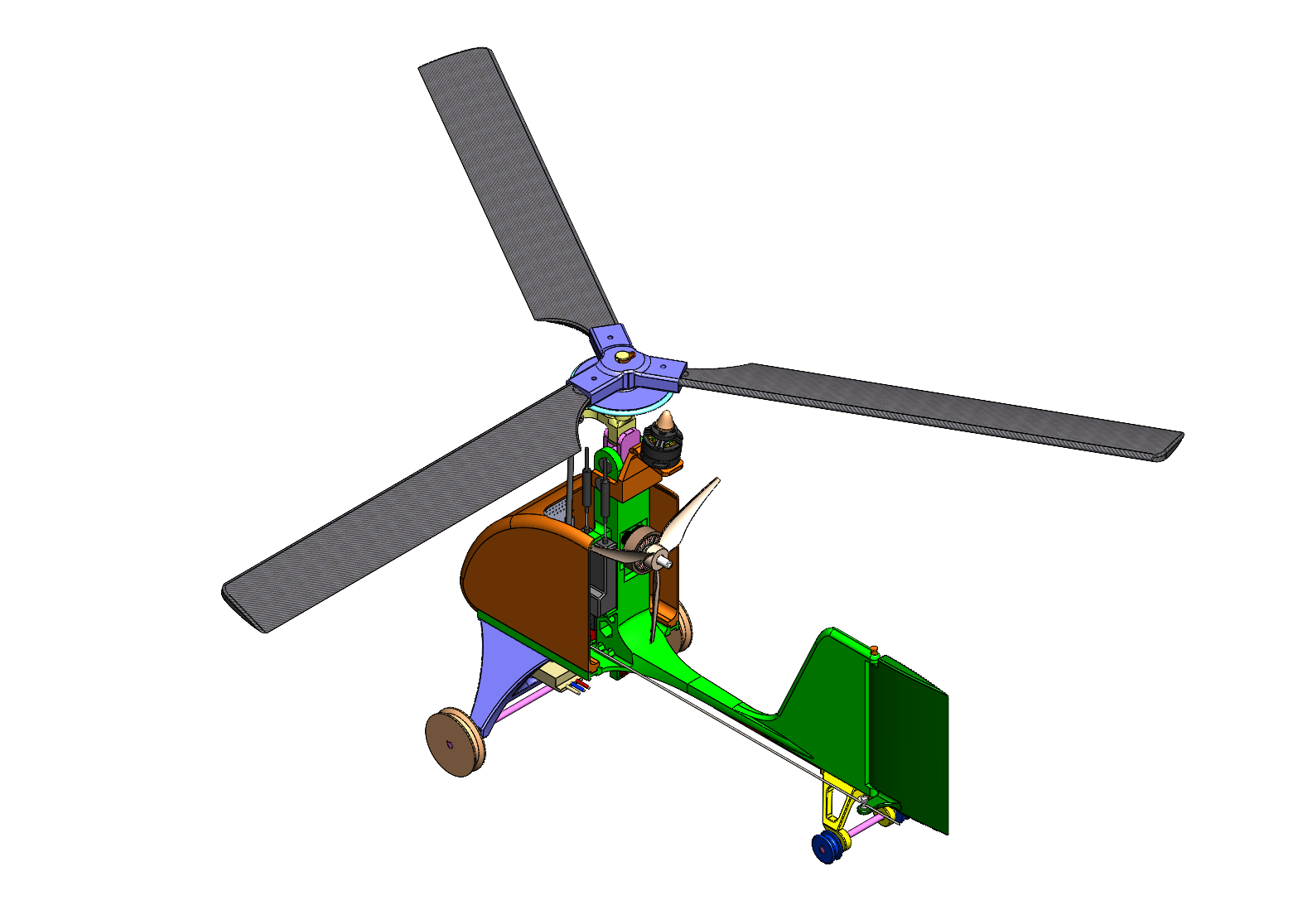
The final design represents a more complete and optimized version of the autogyro. After the design was validated through PLA prototypes, the final version was printed in ASA Aero to reduce overall weight. Although the canopy originally included lightening holes, those features had to be removed because they made ASA Aero printing difficult and unreliable. Even with the holes removed, weight was still reduced through the material choice.
Additional design changes were also made to improve performance and functionality, including increasing the overall body length to move the empennage out of a dead zone in the incoming airflow, changing from a two-blade to a three-blade rotor configuration, selecting a more powerful motor, and redesigning the landing gear to perform better in surf-like ground conditions.
5. Key Takeaways
This project strengthened my experience in SolidWorks, design iteration, and technical communication. It also reinforced the importance of balancing aerodynamic performance, manufacturability, material choice, and system-level design decisions throughout a full engineering project.